
Dome Devices
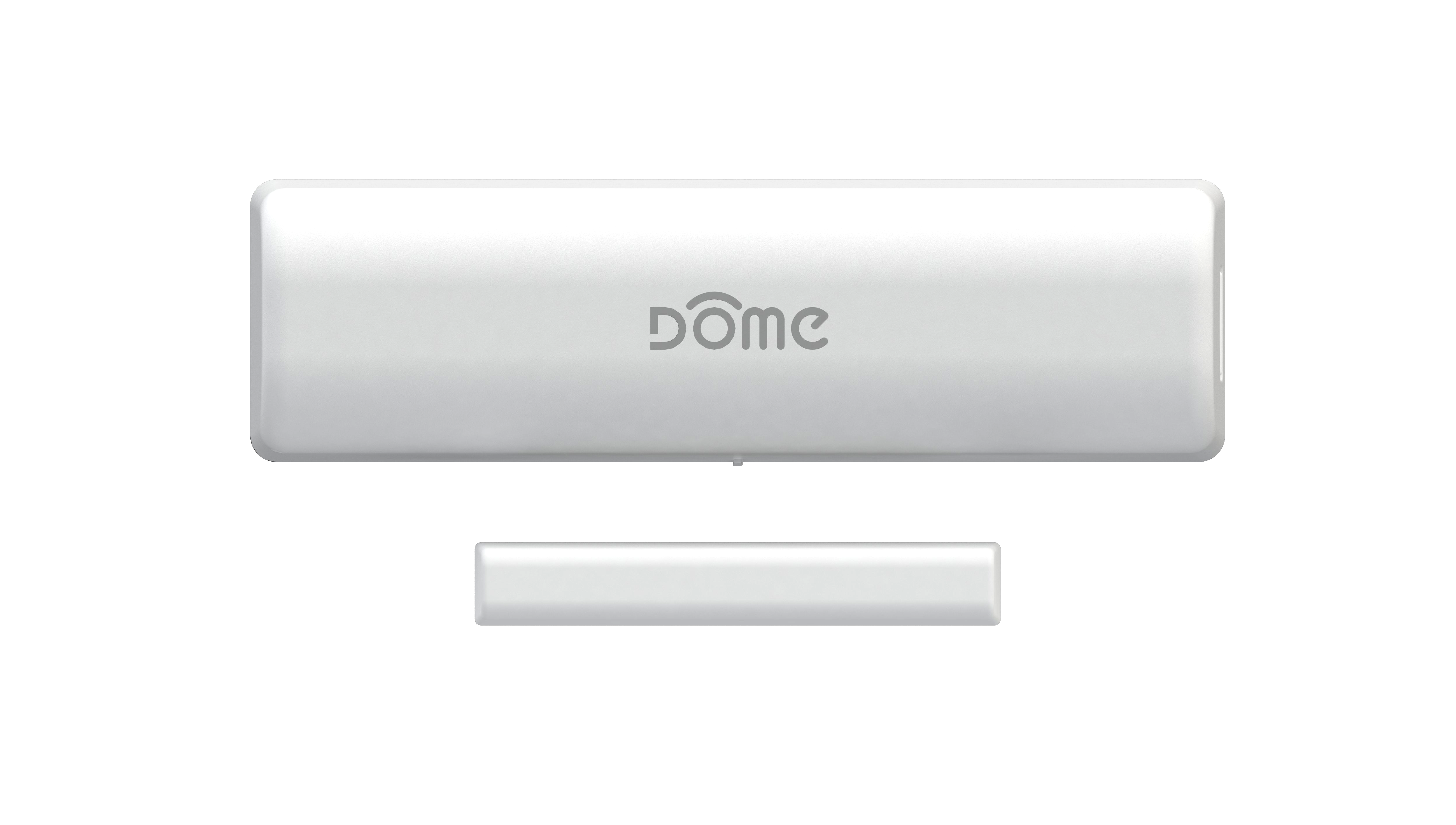
Door/Window Sensor

Description & Features
The Dome Door/Window Sensor is a battery powered Z-Wave Plus magnetic reed switch that can monitor the status of doors, windows, and anything else that opens and closes. The Door/Window Sensor consists of two parts - the “sensor,” and the “magnet.” The sensor has a “reed switch” inside, which is sensitive to the magnet’s presense when aligned properly and within the defined distance. When the sensor and magnet are brought together or pulled apart, the sensor will report its open/close status to its Z-Wave controller.
Key Features
- Z-Wave Plus Certified
- Up to 150’ range
- Three-Year Battery Life
- Low Battery Indication
- 0.5” Max distance between sensor & magnet
- Monitor doors, windows, medicine cabinets, drawers, garage doors, and many other openings
Specifications
Technical Specifications
| Spec | Value |
|---|---|
| Radio protocol | Z-Wave(500 series) |
| Power supply | Single CR14250 (1/2AA) 3.6V battery |
| Standby current | 2.5uA |
| Working current | 35mA |
| Operating temperature | 32 - 104 °F (0 - 40 °C) |
| Radio frequency | 908.4 MHz US |
| Range | Up to 150’ depending on environment |
| Dimensions (L x W x H) |
Sensor: 2.75” x 0.8” x 0.8” (70 x 20 x 20 mm) Magnet: 1.3” x 0.5” x 0.5” (40 x 11 x 11 mm) |
| Package Contents | User Manual, Sensor, Magnet, Battery, 4x Screws, 4x Wall Anchors, Double Stick Tape |
Inclusion & Exclusion
Figure 1 - Exploded View
Inclusion
- For proper inclusion, bring the Door/Window Sensor to the final location where it will be used.*
- Remove the SENSOR COVER.
- Remove the BATTERY TAB.
- Press the BUTTON quickly 3 times in a row.
A red LED will flash five times indicating inclusion.
Exclusion
Follow the instructions for your Z-Wave Certified Conto enter exclusion mode. When prompted by the controller:
- Remove the SENSOR COVER.
- Press the BUTTON button quickly 3 times in a row.
A red LED will flash five times indicating exclusion/disconnection.
Factory Reset & Misc. Functions
Resetting the Door/Window Sensor
If needed, the Door/Window Sensor can be reset locally by following these steps.
- Remove the SENSOR COVER and confirm that your Door/Window Sensor is powered up.
- Press and hold the BUTTON for at least 10 seconds then release. A flashing light indicates a successful factory reset.
The Door/Window Sensor’s memory will be erased to factory settings.
Waking Up the Door/Window Sensor
Because the Door/Window Sensor is a battery powered device, it wakes up on regular intervals to give battery and other status updates to the controller, as well as to accept configuration settings from the controller. This helps to extend the battery life. The device can be forced to wake up to submit these reports or accept new settings immediately by simply pressing and holding the BUTTON for half a second. The LED INDICATOR will flash once indicating successful wake up.
Physical Installation
The Door/Window Sensor can be secured with the pre-applied double stick tape or the provided hardware. The device should already be included in your Z-Wave system before continuing further.
Figures 3 & 4 - Showing the Door/Window Sensor Installation Location and Sensor Alignment
Pre-Installation Checklist
- The MAGNET and SENSOR should be less than 1/2” apart when closed (Figure 4.)
-
Hold the magnet and sensor in place by hand where you wish to install them, move them in
and out of the closed position, and make sure the INDICATOR LED blinks in response. This
will confirm that the door and frame are spaced correctly to accommodate the sensor.
- Make sure the SENSOR COVER RELEASE BUTTON will be accessible in the final position.
- Finally, confirm that you are still within range of your Z-Wave controller.
Installation Using Double-Stick Tape
- Wipe the door and doorframe clean of dust and anything else that will interfere with the tape’s stickiness.
- Peel the double-stick tape and adhere the SENSOR to the door surface.
- Repeat the process for the MAGNET, making sure the MAGNET and SENSOR are no more than 1/2” apart when closed. The lines on the sides of the MAGNET and SENSOR should be in line.
- Open and close the door to make sure the sensor works as expected (the INDICATOR LED blinks) and that the signal reaches your Z-Wave controller.
Installation Using Screws
Figure 5 - Installing the Door/Window Sensor with Screws.
- Remove the SENSOR COVER and BATTERY from the SENSOR BASE and the MAGNET COVER from the MAGNET BASE.
- Hold the SENSOR BASE in place and drive the included screws through the screw holes into the door.
- Repeat the process for the MAGNET, making sure the MAGNET and SENSOR are no more than 1/2” apart when the door is closed. The lines on the sides of the MAGNET and SENSOR should be in line.
- Replace the BATTERY, SENSOR COVER, and MAGNET COVER.
- Open and close the door to make sure the sensor works as expected (the INDICATOR LED blinks) and that the signal reaches your Z-Wave controller.
LED Behavior
| Color | Behavior | This happens when… |
|---|---|---|
| Red | Blink 5 times in 5 seconds (slow) | …the Door/Window Sensor was just powered on, but is not yet included in a system. |
| Blink 5 times in 2.5 seconds (medium) | …the BUTTON is pressed 3 times quickly (regardless of inclusion status.) | |
| Blink 5 times in 1.5 seconds (fast) | …the Door/Window Sensor is powered on, and already included in a system. | |
| Stay on for 2+ seconds straight | …the BUTTON is pressed and held for 10+ seconds, resetting Door/Window Sensor to factory settings. | |
| Blinks once for 1 second | …the SENSOR detects the MAGNET getting close or moving away (when the door opens or closes.) | |
| Blinks once | …the BUTTON is pushed once. |
Table 2 - LED Behavior
Button Behavior
| Action | Condition | Result |
|---|---|---|
| Press and hold BUTTON for 2 seconds | Door/Window Sensor Already Included in System | Device sends a wake up notification to its controller, awaits further instructions, and blinks the LED Indicator once |
| Push BUTTON 3 Times | Door/Window Sensor Already Included in System | Device sends node info to Group 1 |
| Door/Window Sensor Already Included, and Controller is in Exclusion Mode | Device is excluded from the system and removes the Home ID from its memory | |
| Door/Window Sensor Not Yet Included in System, and Controller is in Inclusion Mode | Device enters inclusion mode and includes into whichever network is also in inclusion mode | |
| Press and hold BUTTON for 10+ seconds | Door/Window Sensor Already Included in System | Device will be reset to factory settings, and a DEVICE_RESET_LOCALLY command will be sent to Node 1 |
| Press and Hold for 10+ seconds | Any condition (as long as the device has power) | The device’s memory will erase to factory default settings and any associations, configuration parameters, and other locally saved data will be lost |
Table 3 - Button Behavior
Compatible Command Classes
| Command Class | Notes | ||||||||||||||||
|---|---|---|---|---|---|---|---|---|---|---|---|---|---|---|---|---|---|
| Device Reset Locally V1 (5A) | - | ||||||||||||||||
| Powerlevel V1 (73) | - | ||||||||||||||||
| Battery V1(80) | - | ||||||||||||||||
| Association Group Information V1 (59) | - | ||||||||||||||||
| Z-Wave Plus Info V2 (5E) |
Returned Value: 01 06 00 0C 06 0C 06
|
||||||||||||||||
| Version V2 (86) |
|
||||||||||||||||
| Manufacturer Specific V2 (72) |
|
||||||||||||||||
| Binary Sensor (30) |
The Door/Window Sensor also sends a Binary Sensor Report when opened or closed. See
below for the SENSOR_BINARY_REPORT parameters sent:
|
||||||||||||||||
| Association V2 (85) |
Group 1
Group 2
Group 3
Group 4
|
||||||||||||||||
| Wake Up V2 (84) | The wake-up interval is set in seconds, and is 43,200 seconds (12 hours) by default. The wake-up interval can be set to any value from 300s (5 minutes) to 16,777,200s (about 190 days) in 60-second increments. | ||||||||||||||||
| Notification V4 (71) |
The Door/Window Sensor sends a Notification Report to the main controller whenever the
door is opened and closed.
|
||||||||||||||||
| Configuration V1(70) | See “Configuration” Command Class Parameters”. |
Table 4 - Compatible Command Classes
“Configuration” Command Class Parameters
Configuration parameters are sent using a standard syntax to ensure interoperability
between all manufacturers’ products. All values are represented using the
hexadecimal number system.
Typical syntax is as shown below. Note that the value
sent must be the exact size, in bytes, as accepted by the setting. The “extra”
spaces should be filled with zeros (see the “value” column below.)
Example Configuration Parameter: 02 02 00 0A
| Param # | Size | Value |
| 02 (Param #2) |
02 (2 Bytes) |
00 0A (Value) |
| Param # | Size | Name | Available Values | Default Value |
|---|---|---|---|---|
| 01 | This parameter sets the delay time from when the Door/Window Sensor sends the BASIC_SET command to Association Group 2 and when the BASIC_SET(0) is sent.,It accepts a value up to 65,535, in seconds. | |||
| 02 | BASIC_SET Off Delay |
00 01 ~ FF FF (1 ~ 65,535 in Seconds) |
1E (30 sec) |
|
| 02 | This parameter sets the value sent by the BASIC_SET command to Association Group 2 (for more information, see “Assocation Groups”.) | |||
| 01 | BASIC_SET Level |
00 (0/Turn Off Device) 01 ~ 63 (1 ~ 99) FF (-1/Turn On Device) |
FF (-1/Turn On Device) |
|
Table 5 - “Configuration” Command Class Parameters
Siren
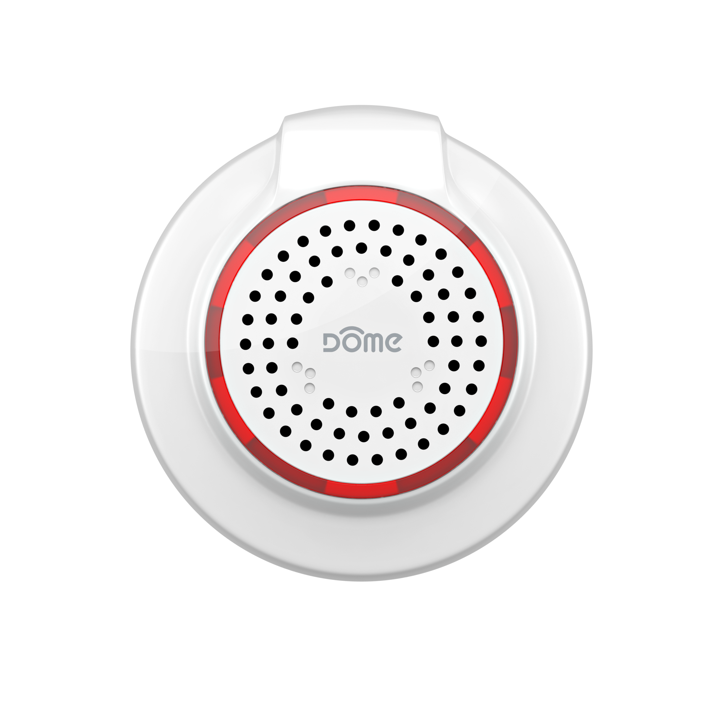
Description & Features
The Dome Siren is a battery powered Z-Wave Plus device that alerts the user to events detected by the connected Z-Wave Controller using an audible alarm. In addition to a 95 Decibel (dB) audible alarm for critical events, the Siren has a secondary chime to signal other events like movement or doors opening.
Key Features
- Z-Wave Plus Certified
- Up to 150’ range
- Three-Year Battery Life
- Low Battery Indication
- 95 dB Audible Alarm (at 1 ft)
- Visual indicator with built-in LED ring
- Secondary Chime
- Customizable notifications and volume levels
Specifications
Technical Specifications
| Spec | Value |
|---|---|
| Radio protocol | Z-Wave(500 series) |
| Power supply | 2x CR123 3.0V battery |
| Power Consumption | 2W |
| Working current | 35mA |
| Operating temperature | 32 - 104 °F (0 - 40 °C) |
| Radio frequency | 908.4 MHz US |
| Range | Up to 150’ depending on environment |
| Dimensions (L x W x H) | Ø2.75" x 1.2" |
| Package Contents | User Manual, Siren, 2x Battery, 1x Screw, 1x Wall Anchor, Double Stick Tape |
Figure 1 - Exploded View
Figure 2 - Showing individual parts A. Inside the Siren and B. Underneath the Siren.
Inclusion & Exclusion
Inclusion
- For proper inclusion, bring the Siren to the final location where it will be used.*
- Remove the BACK COVER.
- Remove the BATTERY TABS.
- Press the BUTTON quickly 3 times in a row.
The LED Ring will flash five times indicating inclusion.
Exclusion
Follow the instructions for your Z-Wave Certified Conto enter exclusion mode. When prompted by the controller:
- Remove the BACK COVER.
- Press the BUTTON button quickly 3 times in a row.
The LED Ring will flash five times indicating exclusion/disconnection.
Factory Reset & Misc. Functions
Resetting the Siren
If needed, the Siren can be reset locally by following these steps.
- Remove the BACK COVER and confirm that your Siren is powered up.
- Press and hold the BUTTON for at least 10 seconds then release. A flashing light indicates a successful factory reset.
The Siren’s memory will be erased to factory settings.
Physical Installation
Pre-Installation Checklist
- The Siren can be mounted on a wall or placed on shelf or tabletop
- The Siren is loud enough to be audible from inside a drawer
- The BACK COVER twists CLOCKWISE to be removed
- The Siren should be included in your Z-Wave System prior to installation
- Confirm that your device can communicate with your Z-Wave Controller from the final installed location before proceeding
Installation Using Double-Stick Tape
- Wipe the surface you wish to attach the Siren to clean of any residue.
- With the Siren completely assembled, peel the preapplied adhesive backing and firmly push it against the wall.
Installation—Using Keyhole Slot
- Drive a screw into the surface the Siren will be attached to, leaving it 1/8” away from being completely flush.
- Slide the fully assembled Siren around the screw, into the keyhole slot, and pull it down to completely secure the device around the screw.
Installation—With Screws
- Remove the BACK COVER by twisting it clockwise.
- Hold the BACK COVER on the surface it will be attached to, and drive two of the included screws through indentations on the BACK COVER. You may optionally install anchors in the wall for added support.
- Twist the MAIN BODY counter clockwise onto the BACK COVER.
LED Behavior
| Color | Behavior | This happens when… |
|---|---|---|
| Red | Blink 5 times in 1 second | …the device powers on, but is not yet included in a Z-Wave Network. |
| Blink 5 times in 500ms | …the CONNECT BUTTON is pushed 3 times, either resulting in the Siren sending its NodeInfo, or being included or excluded from a Z-Wave network. | |
| Blink 5 times in 300ms | …the device powers on, and is arleady included in a Z-wave network. | |
| Blink Once | …the CONNECT BUTTON is pressed for an extended period of time, resetting the Siren to factory default settings. | |
| Flashing and Spinning | …the Siren is sounding its alarm. |
Table 2 - LED Behavior
Button Behavior
| Action | Condition | Result |
|---|---|---|
| Press and hold BUTTON for 2 seconds | Siren Already Included in System | Device sends a wake up notification to its controller, awaits further instructions, and blinks the LED Ring once |
| Push BUTTON 3 Times | Siren Already Included in System | Device sends node info to Group 1 |
| Siren Already Included, and Controller is in Exclusion Mode | Device is excluded from the system and removes the Home ID from its memory | |
| Siren Not Yet Included in System, and Controller is in Inclusion Mode | Device enters inclusion mode and includes into whichever network is also in inclusion mode | |
| Press and hold BUTTON for 10+ seconds | Siren Already Included in System | Device will be reset to factory settings, and a DEVICE_RESET_LOCALLY command will be sent to Node 1 |
| Press and Hold for 10+ seconds | Any condition (as long as the device has power) | The device’s memory will erase to factory default settings and any associations, configuration parameters, and other locally saved data will be lost |
Table 3 - Button Behavior
Compatible Command Classes
| Command Class | Notes | ||||||||||||||||
|---|---|---|---|---|---|---|---|---|---|---|---|---|---|---|---|---|---|
| Device Reset Locally V1 (5A) | - | ||||||||||||||||
| Powerlevel V1 (73) | - | ||||||||||||||||
| Battery V1(80) | - | ||||||||||||||||
| Association Group Information V1 (59) | - | ||||||||||||||||
| Z-Wave Plus Info V2 (5E) |
Returned Value: 01 07 00 0F 00 0F 00
|
||||||||||||||||
| Version V2 (86) |
|
||||||||||||||||
| Manufacturer Specific V2 (72) |
|
||||||||||||||||
| Association V2 (85) |
Group 1
Group 2
Group 3
|
||||||||||||||||
| Notification V4 (71) |
The Siren sends a Notification Report whenever it is turned on, and another report
when the sound is turned off (either by the user, or by timing out; see Configuration
Parameters 2 and 3.) The Sequence Byte is used to help the Controller keep track of
multiple siren events—if a chime is sounded while another chime is active, the
sequence numbers will increment with each event, resetting back to 01 when no chime
events are active. See below for the NOTIFICATION_REPORT parameters sent:
|
||||||||||||||||
| Indicator (87) |
The Indicator command class is used to trigger any one of ten different secondary
notifications available to the Siren (the Binary Switch command class is used to
trigger the primary notification.) See Configuration Parameters 3 & 4 for more
information relevant to the secondary chime. See below for the Indicator Set values
The Siren will respond to:
|
||||||||||||||||
| Binary Switch (25) |
The Siren will respond to BINARY_SWITCH_SET(FF) and BINARY_ SWITCH_SET(00) commands by
turning on and off, respectively, the Siren (primary) notification sound. The Siren
also sends a Binary Switch Report when it turns on and another report when the sound
is turned off (either by the user, or by timing out; see Configuration Parameters 2
and 3.) See below for the Binary Switch Report parameters sent:
|
||||||||||||||||
| Configuration V1(70) | See “Configuration” Command Class Parameters”. |
Table 4 - Compatible Command Classes
“Configuration” Command Class Parameters
Configuration parameters are sent using a standard syntax to ensure interoperability
between all manufacturers’ products. All values are represented using the
hexadecimal number system.
Typical syntax is as shown below. Note that the value
sent must be the exact size, in bytes, as accepted by the setting. The “extra”
spaces should be filled with zeros (see the “value” column below.)
Example Configuration Parameter: 02 02 00 0A
| Param # | Size | Value |
| 02 (Param #2) |
02 (2 Bytes) |
00 0A (Value) |
| Param # | Size | Name | Available Values | Default Value |
|---|---|---|---|---|
| 01 | This parameter sets the volume of the Siren (primary) sound. There are three possible volume levels available. | |||
| 01 | Primary Notification Volume Level |
01 (Low Volume) 02 (Medium Volume) 03 (High Volume) |
03 (High Volume) |
|
| 02 | This parameter defines the length of the Alarm/primary notification. | |||
| 01 | Primary Notification Length |
01 (30 Seconds) 02 (1 Minute) 03 (5 Minutes) FF (Plays Until Battery is Depleted) |
02 (1 Minute) |
|
| 03 | This parameter defines the number of times the Chime/Secondary Notification will play. | |||
| 01 | Secondary Notification Length |
00 (Chime Will Not Play) 01~FE (1~254 Cycles) FF (Does Not Stop) |
01 (Chime Plays Once) |
|
| 04 | This parameter sets the volume of the Chime (secondary) sound. There are three possible volume levels available. | |||
| 01 | Secondary Notification Volume Level |
01 (Low Volume) 02 (Medium Volume) 3 (High Volume) |
01 (Low Volume) |
|
| 05 | The Siren offers ten different sounds to use as the Siren (primary) notification. This parameter sets the Siren (primary) notification sound. | |||
| 01 | Primary Notification Sound | 01 ~ 0A (Sound Index Number) | 0A | |
| 06 | If Parameter 7 is set to 02, the Siren will play a secondary chime sound instead of the main alarm. The Siren offers ten different sounds to use as the Chime (secondary) notification. This parameter sets the Chime (secondary) notification sound. | |||
| 01 | Secondary Notification Sound | 01 ~ 0A (Sound Index Number) | 09 | |
| 07 | This Parameter toggles between the Primary and Secondary notification sound to be played when the Siren receives a BINARY_SWITCH_SET(FF) command. | |||
| 01 | Toggle Secondary Chime |
01 (Primary Notification Will Play) 02 (Secondary Notification Will Play) |
01 (Primary Notification Will Play) |
|
| 08 | This Parameter enables or disables the Flashing LED Ring (strobe) accompanying the Primary Notification. | |||
| 01 | Enable/Disable Primary Notification Strobe |
00 (LED Ring Will Not Flash) 02 (LED Ring Will Flash) |
01 (LED Ring Will Flash) |
|
| 09 | This Parameter enables or disables the Flashing LED Ring (strobe) accompanying the Secondary Notification. | |||
| 01 | Enable/Disable Secondary Notification Strobe |
00 (LED Ring Will Not Flash) 02 (LED Ring Will Flash) |
00 (LED Ring Will Not Flash) |
|
Table 5 - “Configuration” Command Class Parameters
Motion Detector

Description & Features
The Dome Motion Detector is a Z-Wave Plus device that monitors areas for movement. It does this using a sensor which detects changes in infrared light. Similar to how lightbulbs “glow” in the “visible” light spectrum, humans and other mammals “glow” in the “infrared” light spectrum, so it is easy to detect this type of movement. The Motion Detector can either be wall mounted or placed on any flat horizontal surface. The MOUNT uses a spherical magnet to hold the SENSOR, so it can point in any direction. The Motion Detector also monitors ambient light levels and reports the data to your Z-Wave Hub.
Key Features
- Z-Wave Plus Certified
- Ambient Light Sensor
- Flexible Mounting Options
- 110° Extra-Wide Coverage Area
- Up to 150’ range
- Three-Year Battery Life
- Low Battery Indication
Specifications
Technical Specifications
| Spec | Value |
|---|---|
| Radio protocol | Z-Wave(500 series) |
| Power supply | Single CR123A 3.0V battery |
| Working current | 35mA |
| Power Consumption | 0.15W |
| Radio frequency | 908.4 MHz US |
| Range | Up to 150’ depending on environment |
| Dimensions (L x W x H) | Sensor: 1.75" Sphere |
| Package Contents | User Manual, Sensor, Battery, 2x Screws, 2x Wall Anchors, Double-Stick Tape |
Inclusion & Exclusion
Figure 1 - Exploded View
Figure 2 - Parts of the A. Sensor Base Front, B. Sensor Base Rear, and C. Mount (Wall Mount)
Inclusion
- For proper inclusion, bring the Motion Detector to the final location where it will be used.*
- Remove the SENSOR COVER by twisting it counterclockwise.
- Remove the BATTERY TAB.
- Press the BUTTON quickly 3 times in a row.
The LED Indicator will flash five times indicating inclusion.
Exclusion
Follow the instructions for your Z-Wave Certified Conto enter exclusion mode. When prompted by the controller:
- Remove the SENSOR COVER.
- Press the BUTTON button quickly 3 times in a row.
The LED Indicator will flash five times indicating exclusion/disconnection.
Factory Reset & Misc. Functions
Resetting the Motion Detector
If needed, the Motion Detector can be reset locally by following these steps.
- Remove the SENSOR COVER and confirm that your Motion Detector is powered up.
- Press and hold the BUTTON for at least 10 seconds then release. A flashing light indicates a successful factory reset.
The Motion Detector’s memory will be erased to factory settings.
Waking Up the Motion Detector
Because the Motion Detector is a battery powered device, it wakes up on regular intervals to give battery and other status updates to the controller, as well as to accept configuration settings from the controller. This helps to extend the battery life. The device can be forced to wake up to submit these reports or accept new settings immediately by simply pressing and holding the BUTTON for half a second. The LED INDICATOR will flash once indicating successful wake up.
Physical Installation
How to Use - Tabletop
Figure 3 - Using the Motion Detector on a tabletop
You can use the facets on the Sensor Body to properly angle the Motion Sensor on a table top or bookshelf to monitor a room.
- Remove the Magnetic Cradle and store it for later use if needed.
- Make sure your device is powered on and that there is enough Z-Wave coverage in your installation location.
- Follow Figure 3 and place the Sensor Body on a flat horizontal surface with an unobstructed view of the area you wish to monitor.
How to Use - Wall Mount
Figure 4 - Motion Detector Wall Mount Configurations
You can mount the Motion Detector on any wall with a central line-of-sight perspective of the area you wish to monitor. See Figure 4 to visualize the Motion Sensor’s coverage area and its optimal positioning. It is best to mount the Motion Detector as high as possible to avoid limiting its effective range with obstacles like tables and chairs.
Installation - With Double-Stick Tape
- Find a good location (Fig 4) with adequate Z-Wave coverage to mount your Motion Sensor.
- Wipe your wall clean of any dirt and grease.
- Peel-and-stick the MOUNT to your wall using the included double-stick tape.
- Place the SENSOR on the MOUNT (MAGNET) at an angle to properly monitor your room, and the magnet will hold the SENSOR in place.
Installation—With Screws
- Find a good location (Fig 4) with adequate Z-Wave coverage to mount your Motion Detector.
- Twist the MOUNT counterclockwise to separate the MOUNT (MAGNET) from the MOUNT (WALL MOUNT).
- Hold the MOUNT (WALL MOUNT) to your wall and drive the included screws through the SCREW HOLES.
- Reattach the MOUNT (MAGNET) to the MOUNT (WALL MOUNT).
- Place the SENSOR on the MOUNT (MAGNET) at an angle to properly monitor your room, and the magnet will hold the SENSOR in place.
LED Behavior
| Color | Behavior | This happens when… |
|---|---|---|
| Red | Blink 5 times in 5 seconds (slow) | …the Motion Detector was just powered on, but is not yet included in a system. |
| Blink 5 times in 2.5 seconds (medium) | …the BUTTON is pressed 3 times quickly (regardless of inclusion status.) | |
| Blink 5 times in 1.5 seconds (fast) | …the Motion Detector is powered on, and already included in a system. | |
| Stay on for 2+ seconds straight | …the BUTTON is pressed and held for 10+ seconds, resetting Motion Detector to factory settings. | |
| Blinks once for 1 second | …the SENSOR detects motion OR the BUTTON is pushed once. |
Table 2 - LED Behavior
Button Behavior
| Action | Condition | Result |
|---|---|---|
| Press and hold BUTTON for 2 seconds | Motion Detector Already Included in System | Device sends a wake up notification to its controller, awaits further instructions, and blinks the LED Indicator once |
| Push BUTTON 3 Times | Motion Detector Already Included in System | Device sends node info to Group 1 |
| Motion Detector Already Included, and Controller is in Exclusion Mode | Device is excluded from the system and removes the Home ID from its memory | |
| Motion Detector Not Yet Included in System, and Controller is in Inclusion Mode | Device enters inclusion mode | |
| Press and hold BUTTON for 10+ seconds | Motion Detector Already Included in System | Device will be reset to factory settings, and a DEVICE_RESET_LOCALLY command will be sent to Node 1 |
| Press and Hold for 10+ seconds | Any condition (as long as the device has power) | The device’s memory will erase to factory default settings and any associations, configuration parameters, and other locally saved data will be lost |
Table 3 - Button Behavior
Compatible Command Classes
| Command Class | Notes | ||||||||||||||||
|---|---|---|---|---|---|---|---|---|---|---|---|---|---|---|---|---|---|
| Device Reset Locally V1 (5A) | - | ||||||||||||||||
| Powerlevel V1 (73) | - | ||||||||||||||||
| Battery V1(80) | - | ||||||||||||||||
| Association Group Information V1 (59) | - | ||||||||||||||||
| Z-Wave Plus Info V2 (5E) |
Returned Value: 01 06 00 0C 07 0C 07
|
||||||||||||||||
| Version V2 (86) |
|
||||||||||||||||
| Manufacturer Specific V2 (72) |
|
||||||||||||||||
| Multilevel Sensor (31) |
The Motion Detector monitors ambient light levels and reports this data to the main
controller using the Multilevel Sensor command class. The light is measured everytime
motion is detected and periodically (every 180 s by default; see Parameter 07.) Each
time the device wakes up or checks the light level, the Param 7 clock is reset. A
report is sent only if the light is at least 100 Lux more intense than the last
reported value.
|
||||||||||||||||
| Binary Sensor (30) |
The Motion Detector also sends a Binary Sensor Report when motion is detected or
cleared. See below for the Binary Sensor Report parameters sent:
|
||||||||||||||||
| Association V2 (85) |
Group 1
Group 2
Group 3
Group 4
|
||||||||||||||||
| Wake Up V2 (84) | The wake-up interval is set in seconds, and is 43,200 seconds (12 hours) by default. The wake-up interval can be set to any value from 300s (5 minutes) to 16,777,200s (about 190 days) in 60-second increments. | ||||||||||||||||
| Notification V4 (71) |
The Motion Detector sends a Notification Report whenever motion is detected. If no
motion is detected for the amount of time set by Configuration Parameter 2, the device
will send another Notification Report to the main controller.
|
||||||||||||||||
| Configuration V1(70) | See “Configuration” Command Class Parameters”. |
Table 4 - Compatible Command Classes
“Configuration” Command Class Parameters
Configuration parameters are sent using a standard syntax to ensure interoperability
between all manufacturers’ products. All values are represented using the
hexadecimal number system.
Typical syntax is as shown below. Note that the value
sent must be the exact size, in bytes, as accepted by the setting. The “extra”
spaces should be filled with zeros (see the “value” column below.)
Example Configuration Parameter: 02 02 00 0A
| Param # | Size | Value |
| 02 (Param #2) |
02 (2 Bytes) |
00 0A (Value) |
| Param # | Size | Name | Available Values | Default Value |
|---|---|---|---|---|
| 01 | This parameter sets the sensitivity of the Motion Detector. It is a unitless parameter ranging in values from 8 up to 255, with 8 being the highest sensitivity level and 255 being the lowest. After physical installation, make sure the farthest part of the coverage area is still “visible” to the Motion Detector by adjusting this parameter. | |||
| 01 | Sensitivity Level |
08 ~ FF (8 ~ 255) |
0C (12) |
|
| 02 | This parameters sets the amount of time after a motion event before the Motion Detector reports no activity to the main controller (see “Notification” and “Binary Sensor” command classes on page 14-15 for more information.) This also sets the amount of time before a BASIC_SET(00) command is sent to Association Group 2 to turn off any activated devices. This value must be higher than the value of Parameter 6, and if this parameter is reset to default settings, Parameter 6 will also be reset. See “Group 2” on page for more information. | |||
| 02 | Motion Cleared Time Delay | 00 05 ~ 02 58 (5 ~ 600 in Seconds) |
1E (30 Sec) |
|
| 03 | This parameter sets the value sent by the BASIC_SET command to Association Group 2 (for more information, see “Association Group Info”.) | |||
| 01 | BASIC_SET Level |
00 (0/Turn Off Device) 01 ~ 63 (0-99) FF (255/Turn On Device) |
FF (255/Turn On Device) |
|
| 04 | This setting enables or disables motion detection and light reporting. | |||
| 01 | Enable/Disable Motion Detector |
00 (Motion Detection Disabled ) 01 (Motion Detection Enabled) |
01 (Motion Detection Enabled) |
|
| 05 | If Parameter 8 is enabled, this setting sets the light level below which the Motion Detector will send BASIC_SET commands to Association Group 2 when motion is detected. For more information, see “Association Group Info”. | |||
| 02 | Group 2 Ambient Light Threshold |
00 05 ~ 03 E8 (5 ~ 1,000 in Lux) |
00 64 (100 Lux) |
|
| 06 | After each motion event, the Motion Detector is disabled for the amount of time set by this parameter before it can send out another “Motion Detected” Notification Report/Binary Sensor Report. This value must be lower than the value of Parameter 2, and if this parameter is reset to default settings, Parameter 2 will also be reset. | |||
| 01 | Retrigger Interval | 01 ~ 08 (1 ~ 8 in seconds) |
8 (8 seconds) |
|
| 07 | This parameter sets the amount of time between each successive ambient light level reading that is sent. This value must be less than the Wakeup Interval Time (which is 43,200 seconds or 12 hours by default.) | |||
| 02 | Light Sensing Interval |
00 3C ~ 8C A0 (60 ~ 36,000 in seconds) |
00 B4 (180 sec) |
|
| 08 | If this parameter is enabled, the Motion Detector will only send Basic Set commands to Associon Group 2 if the ambient light level is below the value set in Parameter 05. For more information, see “Association Group Info.“ | |||
| 01 | Enable/Disable Group 2 Ambient Light Threshold |
00(Group 2 Ambient Light Threshold Disabled) 01(Group 2 Ambient Light Threshold Enabled) |
00 (Ambient Light Threshold Disabled) |
|
| 09 | This Parameter sets the minimum change in ambient light level (in lux) the Motion Detector must detect before a Multilevel Sensor Report is sent to the main controller. | |||
| 01 | Ambient Light Sensitivity Level | 00 ~ FF (0 ~ 255 in Lux) |
64 (100 Lux) |
|
| 0A | If this parameter is enabled, the LED INDICATOR will flash everytime there motion is detected. If this is disabled, the LED INDICATOR will not flash to indicate motion events. | |||
| 01 | Enable/Disable LED INDICATOR |
00(LED Disabled) 01(LED Enabled) |
01 (LED Enabled) |
|
Table 5 - "Configuration” Command Class Parameters
Leak Sensor

Description & Features
The Dome Leak Sensor is a battery powered Z-Wave Plus device that can detect wetness and send a notification when it does so. The Leak Sensor consists of two parts—the “SENSOR ASSEMBLY,” and the optional “REMOTE SENSOR PROBE.” They both detect water similarly, using three visible “LEAD.” The moment water touches any of the LEAD, the device will beep and send a notification with its moisture status to its Z-Wave controller. The REMOTE SENSOR PROBE is used to monitor confined or otherwise difficult to reach places.
Key Features
- Z-Wave Plus Certified
- Beeps and sends Z-Wave notification when water is detected
- Thin profile—can fit under appliances
- Remote Sensor Probe with 4’ extension for hard-to-reach areas
- Up to 150’ range
- Three-Year Battery Life
- Low Battery Indication
- Good to place near washing machines, dishwashers, sinks, toilets, or your indoor garden to alert you of any leaky accidents!
Specifications
Technical Specifications
| Spec | Value |
|---|---|
| Radio protocol | Z-Wave(500 series) |
| Power supply | Single CR2 3.0V battery |
| Working current | 35mA |
| Power Consumption | 0.13W |
| Radio frequency | 908.4 MHz US |
| Range | Up to 150’ depending on environment |
| Dimensions (L x W x H) | Sensor: Ø2.63” x 1” |
| Package Contents | User Manual, Sensor, Sensor Cradle, Remote Sensor Prove, Battery, 1x Screws, 1x Wall Anchors |
Inclusion & Exclusion
Figure 1 - Exploded View
Figure 2 - Parts of the A. Main Body Base, B. Main Body Cover, and C. Main Body Cradle
Inclusion
- For proper inclusion, bring the Leak Sensor to the final location where it will be used.*
- Remove the MAIN BODY COVER by twisting it counterclockwise.
- Remove the BATTERY TAB.
- Press the BUTTON quickly 3 times in a row.
The LED Indicator will flash five times indicating inclusion.
Exclusion
Follow the instructions for your Z-Wave Certified Conto enter exclusion mode. When prompted by the controller:
- Remove the MAIN BODY COVER.
- Press the BUTTON button quickly 3 times in a row.
The LED Indicator will flash five times indicating exclusion/disconnection.
Factory Reset & Misc. Functions
Resetting the Leak Sensor
If needed, the Leak Sensor can be reset locally by following these steps.
- Remove the MAIN BODY COVER and confirm that your Leak Sensor is powered up.
- Press and hold the BUTTON for at least 10 seconds then release. A flashing light indicates a successful factory reset.
The Leak Sensor’s memory will be erased to factory settings.
Waking Up the Leak Sensor
Because the Leak Sensor is a battery powered device, it wakes up on regular intervals to give battery and other status updates to the controller, as well as to accept configuration settings from the controller. This helps to extend the battery life. The device can be forced to wake up to submit these reports or accept new settings immediately by simply pressing and holding the BUTTON for half a second. The LED INDICATOR will flash once indicating successful wake up.
Physical Installation
The device should already be included in your Z-Wave system before continuing further. Study the Pre-Installation Checklist below for a broad overview of installation options and other notes to bear in mind.
Pre-Installation Checklist
- The MAIN BODY CRADLE and REMOTE SENSOR PROBE are optional, to help monitor hard-to-reach areas—study Figures 3 and 4 to understand when, where, and why to use the REMOTE SENSOR PROBE
- The Leak Sensor detects moisture the moment water contacts the METAL FEET on the REMOTE SENSOR PROBE or the MAIN BODY BASE
- To monitor a pipe or appliance for leaks, place the Leak Sensor nearby on a flat surface where water is likely to accumulate during a leak
- If there is not enough space for the SENSOR ASSEMBLY to fit, use the optional REMOTE SENSOR PROBE
- When using the REMOTE SENSOR PROBE, the SENSOR ASSEMBLY will rest in the MAIN BODY CRADLE
- All three METAL FEET should contact the surface
- The REMOTE SENSOR PROBE can also hang mid-air to monitor rising water levels (for example in a sump pump pit)
Figures 3 & 4 - Installing the Leak Sensor Near a Toilet or Appliance.
Installation—Without the REMOTE SENSOR PROBE
-
Make sure the Leak Sensor is already included in your Z-Wave System and bring it to your
desired installation location.
- Confirm that your device can communicate with your Z-Wave Controller from the final installed location before proceeding.
- Place the SENSOR ASSEMBLY on a flat surface near the device to be monitored (see “Pre-Installation Checklist” on page <?> for proper placement instructions.)
- Double-check that your Z-Wave Controller can still communicate with the Leak Sensor, and pour a small amount of water on the floor to emulate a leak and confirm that the device beeps and reports the event to your Controller.
Installation—With the REMOTE SENSOR PROBE
Hard to reach areas can be monitored for leaks using the included REMOTE SENSOR PROBE (see “Pre-Installation Checklist” on page <?>.)
- Mount the MAIN BODY CRADLE on a wall near the location you wish to monitor, making sure the REMOTE SENSOR PROBE’s cable will reach it comfortably. You may optionally rest the MAIN BODY CRADLE, unmounted, on a table, shelf, or other surface.
- Snap the SENSOR ASSEMBLY into the MAIN BODY CRADLE, making sure the METAL FEET on the SENSOR ASSEMBLY line up with their mates on the MAIN BODY CRADLE.
- Plug the REMOTE SENSOR PROBE into the MAIN BODY CRADLE and place the other end of the PROBE in the area to monitor, making sure the METAL FEET are flat on the surface.
LED Behavior
| Color | Behavior | This happens when… |
|---|---|---|
| Red | Blink 5 times in 5 seconds (slow) | …the Leak Sensor was just powered on, but is not yet included in a system. |
| Blink 5 times in 2.5 seconds (medium) | …the CONNECT BUTTON is pressed 3 times quickly (regardless of inclusion status.) | |
| Blink 5 times in 1.5 seconds (fast) | …the Leak Sensor is powered on, and already included in a system. | |
| Stay on for 2+ seconds straight | …the CONNECT BUTTON is pressed and held for 10+ seconds, resetting Leak Sensor to factory settings. | |
| Blinks while Beeping | …the SENSOR detects a leak. | |
| Blinks once | …the CONNECT BUTTON is pushed once. |
Table 2 - LED Behavior
Button Behavior
| Action | Condition | Result |
|---|---|---|
| Press the CONNECT BUTTON for 0.5 second | Leak Sensor Already Included in System | Device sends a wake up notification to its controller, awaits further instructions, and blinks the LED Indicator once |
| Push CONNECT BUTTON 3 Times | Leak Sensor Already Included in System | Device sends node info to Group 1 |
| Leak Sensor Already Included, and Controller is in Exclusion Mode | Device is excluded from the system and removes the Home ID from its memory | |
| Leak Sensor Not Yet Included in System, and Controller is in Inclusion Mode | Device enters inclusion mode and includes into whichever network is also in inclusion mode | |
| Press and hold CONNECT BUTTON for 10+ seconds | Leak Sensor Already Included in System | Device will be reset to factory settings, and a DEVICE_RESET_LOCALLY command will be sent to Node 1 |
| Press and Hold for 10+ seconds | Any condition (as long as the device has power) | The device’s memory will erase to factory default settings and any associations, configuration parameters, and other locally saved data will be lost |
Table 3 - Button Behavior
Compatible Command Classes
| Command Class | Notes | ||||||||||||||||
|---|---|---|---|---|---|---|---|---|---|---|---|---|---|---|---|---|---|
| Device Reset Locally V1 (5A) | - | ||||||||||||||||
| Powerlevel V1 (73) | - | ||||||||||||||||
| Battery V1(80) | - | ||||||||||||||||
| Association Group Information V1 (59) | - | ||||||||||||||||
| Z-Wave Plus Info V2 (5E) |
Returned Value: 01 06 00 0C 05 0C 05
|
||||||||||||||||
| Version V2 (86) |
|
||||||||||||||||
| Manufacturer Specific V2 (72) |
|
||||||||||||||||
| Binary Sensor (30) |
The Leak Sensor also sends a Binary Sensor Report when a leak is detected or removed.
See below for the SENSOR_BINARY_REPORT parameters sent:
|
||||||||||||||||
| Association V2 (85) |
Group 1
Group 2
Group 3
Group 4
|
||||||||||||||||
| Wake Up V2 (84) | The wake-up interval is set in seconds, and is 43,200 seconds (12 hours) by default. The wake-up interval can be set to any value from 300s (5 minutes) to 16,777,200s (about 190 days) in 60-second increments. | ||||||||||||||||
| Notification V4 (71) |
The Leak Sensor sends a Notification Report whenever a leak is detected or removed.
|
||||||||||||||||
| Configuration V1(70) | See “Configuration” Command Class Parameters”. |
Table 4 - Compatible Command Classes
“Configuration” Command Class Parameters
Configuration parameters are sent using a standard syntax to ensure interoperability
between all manufacturers’ products. All values are represented using the
hexadecimal number system.
Typical syntax is as shown below. Note that the value
sent must be the exact size, in bytes, as accepted by the setting. The “extra”
spaces should be filled with zeros (see the “value” column below.)
Example Configuration Parameter: 02 02 00 0A
| Param # | Size | Value |
| 02 (Param #2) |
02 (2 Bytes) |
00 0A (Value) |
When the Leak Sensor detects a leak, it beeps intermittently in the pattern shown in Figure 5. Total Alarm Duration, Mute Time, Initial Alarm, and Reminder Alarm duration times are all configurable using Configuration Parameters 1, 2, 3, and 4 respectively.
Figures 5 - Leak Sensor Audible Alarm Behavior.
| Param # | Size | Name | Available Values | Default Value |
|---|---|---|---|---|
| 01 | This parameter sets the total amount of time the Leak Sensor will beep and light its LED in the event of a leak (see Figure 5.) | |||
| 01 | Total Alarm Duration |
00 (Leak Sensor beeps until water is removed) 01 ~ FF (1 ~ 255 in Minutes) |
78 (120 min) |
|
| 02 | This parameter defines the amount of time the Leak Sensor remains quiet between each Reminder Alarm (see Fig 5.) | |||
| 01 | Mute Time | 01 ~ FF (1 ~ 255 minutes) |
01 (1 min) |
|
| 03 | This parameter sets the amount of time the Leak Sensor beeps before it is muted (see Fig 5.) | |||
| 01 | Initial Alarm |
0A ~ FF (0/Turn Off Device) |
3C (60 sec) |
|
| 04 | This parameter sets the length of each beep after the Initial Alarm (see Fig 5.) | |||
| 01 | Reminder Alarm | 05 ~ FF (5 ~ 255 seconds) |
05 (5 sec) |
|
| 05 | This parameter enables or disables the audible alarm (“beeping”) functionality of the Leak Sensor. | |||
| 01 | Enable/Disable Audible Alarm |
00 (Audible Alarm Disabled) 01 (Audible Alarm Enabled) |
01 (Audible Alarm Enabled) |
|
| 06 | This parameter enables or disables the Leak Sensor - if disabled, the device will not respond in any way to detected leaks. | |||
| 01 | Enable/Disable Water Detection |
00 (Water Detection Disabled) 01 (Water Detection Enabled) |
01 (Water Detection Enabled) |
|
| 07 | This parameter defines the value sent by the BASIC_SET command to Association Group 2 (for more information, see “Assocation Groups”.) | |||
| 01 | Basic Set Level |
00 (0/Turn Off Device) 01 ~ 63 (0-99) FF (-1/Turn On Device) |
FF (-1/Turn On Device) |
|
Table 5 - “Configuration” Command Class Parameters
On/Off Plug-In Switch
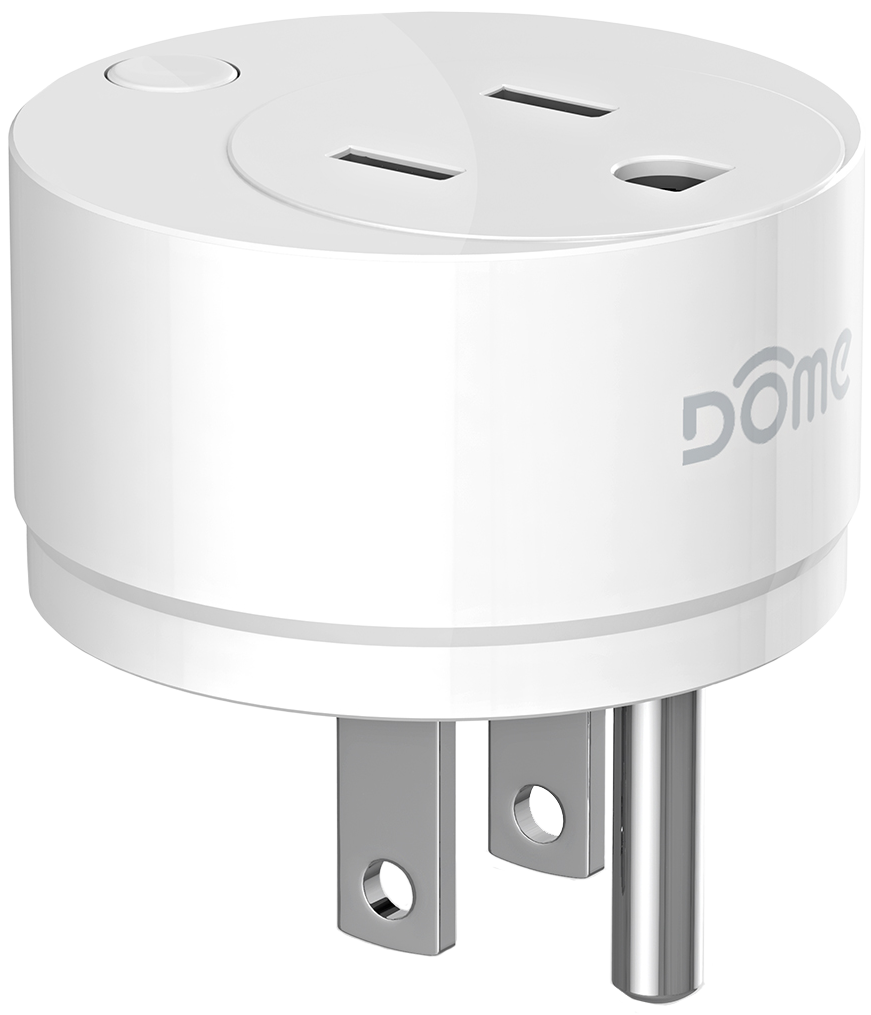
Description & Features
The Dome On/Off Plug-In Switch is a Z-Wave Plus device that plugs into a standard 3-prong power outlet and lets you turn on or off any connected electronic device. The On/Off Plug-In Switch also monitors how much energy the attached device uses, and reports the data to your Z-Wave Hub.
Key Features
- Z-Wave Plus Certified
- Turns on or off any plugged-in device
- Extends the range of your Z-Wave system
- Up to 150’ range
- Small size - won’t block the adjacent outlet!
- Fits any standard 3-prong American power outlet
- Reports energy consumption data
- Overload protection
- Max current - 13 A
Specifications
Technical Specifications
| Spec | Value |
|---|---|
| Radio protocol | Z-Wave(500 series) |
| Power supply | 110-230V AC 50/60Hz |
| Max current | 13A |
| Power Consumption | 0.13W |
| Radio frequency | 908.4 MHz US |
| Range | Up to 150’ depending on environment |
| Dimensions (L x W x H) | Sensor: 1.8" x 1.8" x 1.8” |
| Package Contents | User Manual, On/Off Plug-In Switch |
Inclusion & Exclusion
Figure 1 - Parts of the On/Off Plug-In Switch
Inclusion
Follow the instructions for your Z-Wave Certified Conto enter inclusion mode. When prompted by the controller:
- For proper inclusion, plug the On/Off Plug-In Switch into the outlet where it will be used.*
- When prompted by the controller, quickly press the BUTTON 3 times.
- A yellow LED will flash five times indicating inclusion.
Exclusion
Follow the instructions for your Z-Wave Certified Conto enter exclusion mode. When prompted by the controller:
- Plug the On/Off Plug-In Switch into an outlet.
- Press the BUTTON button quickly 3 times in a row.
A yellow LED will flash five times indicating exclusion/disconnection.
Factory Reset & Misc. Functions
Resetting the On/Off Plug-In Switch
If needed, the On/Off Plug-In Switch can be reset locally by following these steps.
- Confirm that your On/Off Plug-In Switch is powered up.
- Press and hold the BUTTON for at least 10 seconds then release. The LED will blink once in a red color followed by 5 times in a pink color indicating a successful factory reset.
The On/Off Plug-In Switch’s memory will be erased to factory settings.
Physical Installation
The On/Off Plug-In Switch can be installed in any standard 3-prong American power outlet. To control or monitor an electronic device, simply plug it into the DEVICE PORT. Make sure there is sufficient Z-Wave coverage in your desired installation location.
LED Behavior
| Color | Behavior | This happens when… |
|---|---|---|
| Pink | Blink 5 times in 1 second | …the device powers on, but is not yet included in a Z-Wave Network. |
| Blink 5 times in 500ms | …the BUTTON is pushed 3 times after the On/Off Plug-In Switch is already in a Z-Wave network, and the device sends a notification with its Node Info. | |
| Blue | Blink 5 times in 300ms | …the device powers on, and is arleady included in a Z-wave network. |
| Yellow | Blink 5 times in 500ms | …the BUTTON is pushed three times, including the On/Off Plug-In Switch into a Z-Wave network. |
| Always On | …the current is above the limit set in Param 4 (12A by default.) | |
| Red | Blink Once | …the BUTTON is pressed for an extended period of time, resetting the On/Off Plug-In Switch to factory default settings. |
| Blink Once a Second | …the current is above the limit set in Param 3 (13A by default.) Power will be shut off; LED and power will return to normal when the current drops below the level set in Param 3 and the BUTTON is pushed once. | |
| Green | Always On | …the On/Off Plug-In Switch is powered on. |
Table 2 - LED Behavior
Button Behavior
| Action | Condition | Result |
|---|---|---|
| Press the BUTTON Once | Param 10 = 1 | Turn Device on or off |
| Param 10 = 0 | Nothing | |
| Push CONNECT BUTTON 3 Times | On/Off Plug-In Switch Already Included in System | Device sends node info to Group 1 |
| On/Off Plug-In Switch Already Included in System and Controller is in Exclusion Mode | Device is excluded from the system and removes the Home ID from its memory | |
| On/Off Plug Not Yet Included in System | Device enters inclusion mode and includes into whichever network is also in inclusion mode | |
| Press and hold CONNECT BUTTON for 10+ seconds | All conditions | Device will be reset to factory settings, and a DEVICE_RESET_LOCALLY command will be sent to Node 1 |
Table 3 - Button Behavior
Compatible Command Classes
| Command Class | Notes | ||||||||||||||||||||||||||||||||||||||||
|---|---|---|---|---|---|---|---|---|---|---|---|---|---|---|---|---|---|---|---|---|---|---|---|---|---|---|---|---|---|---|---|---|---|---|---|---|---|---|---|---|---|
| Device Reset Locally V1 (5A) | - | ||||||||||||||||||||||||||||||||||||||||
| Powerlevel V1 (73) | - | ||||||||||||||||||||||||||||||||||||||||
| Association Group Information V1 (59) | - | ||||||||||||||||||||||||||||||||||||||||
| Binary Switch V1 (25) | - | ||||||||||||||||||||||||||||||||||||||||
| All Switch V1 (27) | - | ||||||||||||||||||||||||||||||||||||||||
| Basic V1 (20) | - | ||||||||||||||||||||||||||||||||||||||||
| Z-Wave Plus Info V2 (5E) |
Returned Value: 01 05 00 07 00 07 00
|
||||||||||||||||||||||||||||||||||||||||
| Version V2 (86) |
|
||||||||||||||||||||||||||||||||||||||||
| Manufacturer Specific V2 (72) |
|
||||||||||||||||||||||||||||||||||||||||
| Association V2 (85) |
Group 1
Group 2
Group 3
|
||||||||||||||||||||||||||||||||||||||||
| Notification V4 (71) |
The On/Off Plug-In Switch sends a NOTIFICATION_REPORT to Group 1 when the current load
passes the level set in Param 3, and another report when it drops back below this
level. See below for the NOTIFICATION_REPORT parameters sent:
|
||||||||||||||||||||||||||||||||||||||||
| Meter V4 (32) |
When enabled (see Param 1,) the On/Off Plug-In Switch sends period updates with
various usage information to Group 1 using the Meter Command Class. These reports are
sent periodically (every 300s by default - see Param 2) as well as when a change in
current is detected (see Param 6.) Voltage—The voltage currently being supplied
by the plug (in V) Current—The current being supplied by the plug (in A)
Power—The power supplied by the plug instantaneously (in W) Energy—The
amount of energy supplied per unit time (in kWh)
|
||||||||||||||||||||||||||||||||||||||||
| Configuration V1(70) | See “Configuration” Command Class Parameters”. |
Table 4 - Compatible Command Classes
“Configuration” Command Class Parameters
Configuration parameters are sent using a standard syntax to ensure interoperability
between all manufacturers’ products. All values are represented using the
hexadecimal number system.
Typical syntax is as shown below. Note that the value
sent must be the exact size, in bytes, as accepted by the setting. The “extra”
spaces should be filled with zeros (see the “value” column below.)
Example Configuration Parameter: 02 02 00 0A
| Param # | Size | Value |
| 02 (Param #2) |
02 (2 Bytes) |
00 0A (Value) |
| Param # | Size | Name | Available Values | Default Value |
|---|---|---|---|---|
| 01 | This parameter enables/disables the METER_REPORT function, which sends periodic reports to Group1 members with information on line voltage, current load, and power & energy consumption. Also see Param 2 & 6. | |||
| 01 | Enable/Disable METER_REPORT |
00 (Disable Meter Functionality) 01 (Enable Meter Functionality) |
01 (Meter Enabled) |
|
| 02 | This parameter sets the amount of time between each successive METER_REPORT signal sent to Group 1 (also see Param 1 & 6.) | |||
| 02 | METER_REPORT Interval | 00 01 ~ FF FF (1 ~ 65,535 in Seconds) |
01 2C (300 Sec) |
|
| 03 | Sets the maximum current the plug will pass before it cuts off power and sends a NOTIFICATION_EVENT_POWER_MANAGEMENT_OVER_LOAD_DETECTED signal to Group 1 and a BASIC_SET(FF) to Group 2. The LED will then blink red once per second until the notification is cleared after the current returns to normal. To clear the NOTIFICATION and start monitoring again, the BUTTON must be pushed once (only after the current is back to normal) or a BINARY_SWITCH_SET(FF) command must be sent. NOTE: this value must be higher than Param 4 | |||
| 01 | Set “Overload” Current Level | 01 ~ 10 (1 ~ 16 in Amps) |
0D (13 Amps) |
|
| 04 | Sets the current level at which the On/Off Plug-In Switch will flash its LED yellow, until the current returns to below this level. It will NOT cut off current to the device; this functions as a visible warning to the user. NOTE: this value must be lower than Param 3 | |||
| 01 | Set “Alert” Current Level | 01 ~ Param(3) (in Amps) |
0C (12 Amps) |
|
| 05 | This parameter enables or disables the indicator LED. | |||
| 01 | Enable/Disable Indicator LED |
00 (Disable LED) 01 (Enable LED) |
01 (LED Enabled) |
|
| 06 | In addition to sending a METER_REPORT to Group 1 in the time interval set by Param 2, the On/Off Plug-In Switch also sends a METER_REPORT when it detects a relative change in current flow. This parameter sets this minimum current change amount, in percent, at which point the On/Off Plug-In Switch will send a METER_REPORT to Group 1. Also see Param 1 & 2. | |||
| 01 | Current change METER_REPORT level |
01 ~ 64 (1 ~ 100 in % change in Amps) |
05 (5%) |
|
| 07 | This parameter sets whether or not the On/Off Plug-In Switch will remember if it was turned on or off when it was last plugged in. If enabled, whenever the device is rebooted (plugged in and out of the main outlet,) it will resume its state from before the reboot. If disabled, it will turn on everytime the device is rebooted. | |||
| 01 | Remember On/Off Status |
00 (Don’t Remember On/Off Status) 01 (Remember On/Off Status) |
01 (Remember Status) |
|
| 08 | If this parameter is enabled, whenever the On/Off Plug-In Switch is turned on, it will automatically turn off after a set amount of time (set in Param 9.) | |||
| 01 | Enable/Disable Timer Function |
00(Disable Timer Functionality) 01(Enable Timer Functionality) |
00 (Timer Disabled) |
|
| 09 | Sets the time interval before the On/Off Plug-In Switch automatically shuts off. See Param 8. | |||
| 02 | Set Timer Time Interval |
00 01 ~ FF FF (1 ~ 65,535 in Minutes) |
00 96 (150 Min) |
|
| 0A | If this parameter is enabled, the user can turn the device on or off using the BUTTON. | |||
| 01 | Enable/Disable BUTTON |
00(Disable Button) 01(Enable Button) |
01 (Button Enabled) |
|
Table 5 - “Configuration” Command Class Parameters
Mouser
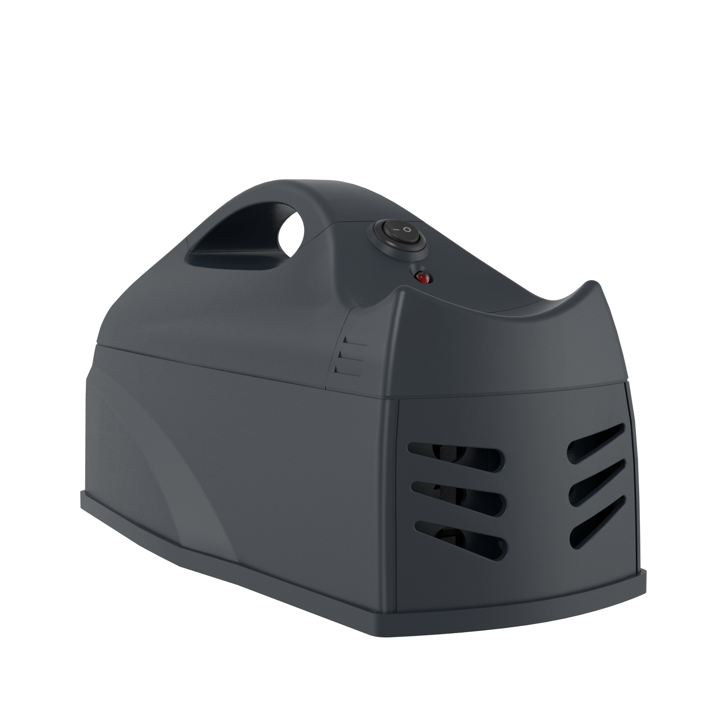
Description & Features
The Dome Mouser is a battery powered Z-Wave Plus enabled mousetrap that works by electrocution and is designed to be humane and painless to the rodent. After a mouse is caught, the Mouser will send a Z-Wave signal to its controller to notify the user, and will not retrigger until the trap is reset.
Key Features
- Z-Wave Plus Certified
- Up to 150’ wireless range, depending on environment
- Quick and painless for both the mouse and the human
- Mess-free rodent removal
- Will work with or without Z-Wave connectivity
- Physical arm/disarm button for added safety
- Two-Year Battery Life—equivalent to 50+ zaps
- Low Battery Indication
Specifications
Technical Specifications
| Spec | Value |
|---|---|
| Radio protocol | Z-Wave(500 series) |
| Power supply | 4x 1.5V AA Size Batteries |
| Working current | 100mA |
| Power Consumption | 0.6W |
| Radio frequency | 908.4 MHz US |
| Range | Up to 150’ depending on environment |
| Dimensions (L x W x H) | Sensor: 8.5” x 4.5” x 5” |
| Package Contents | User Manual, Mouser |
Inclusion & Exclusion
Figure 1 - Parts of the Mouser
Figure 2 - Removing the Bait Holder
Inclusion
- For proper inclusion, bring the Mouser to the final location where it will be used.*
- Remove top cover by sliding it back and lifting up.
- Insert batteries.
- Press the CONNECT BUTTON quickly 3 times in a row.
The LED Indicator will flash five times indicating inclusion.
Exclusion
Follow the instructions for your Z-Wave Certified Conto enter exclusion mode. When prompted by the controller:
- Remove top cover by sliding it back and lifting up.
- Press the CONNECT BUTTON button quickly 3 times in a row.
The LED Indicator will flash five times indicating exclusion/disconnection.
Factory Reset & Misc. Functions
Resetting the Mouser
If needed, the Mouser can be reset locally by following these steps.
- Remove the TOP COVER and confirm that your Mouser is powered up.
- Press and hold the CONNECT BUTTON for at least 10 seconds then release. A flashing LED INDICATOR indicates a successful factory reset.
- The Mouser’s memory will be erased to factory settings.
The Mouser’s memory will be erased to factory settings.
Waking Up the Mouser
Because the Mouser is a battery powered device, it wakes up on regular intervals to give battery and other status updates to the controller, as well as to accept configuration settings from the controller. This helps to extend the battery life. The device can be forced to wake up to submit these reports or accept new settings immediately by simply pressing and holding the BUTTON for half a second. The LED INDICATOR will flash once indicating successful wake up.
Physical Installation
How to Use—Baiting the Trap
- Lift the BAIT HOLDER from the Mouser.
- Add bait - dry foods (like peanuts) leave less mess.
- Replace the BAIT HOLDER.
How to Use—Setting the Trap
- Bait the Mouser.
- Place the Mouser in the desired location - rodents usually scurry around walls and other corners.
- Flip On/Off Button to the On position - the LED will stay lit for two seconds indicating the Mouser is armed. A flashing LED indicates low battery.
- When the Mouser is tripped. the LED will blink every five seconds, and an alert will be sent to your Z-Wave Controller.
- Flip the On/Off Button to the Off position to empty the Mouser, andit is ready to use again immediately.
LED Behavior
| Color | Behavior | This happens when… |
|---|---|---|
| Red | Blink 5 times in 5 seconds (slow) | …the Mouser was just powered on, but is not yet included in a system. |
| Blink 5 times in 2.5 seconds (medium) | …the CONNECT BUTTON is pressed 3 times quickly (regardless of inclusion status.) | |
| Blink 5 times in 1.5 seconds (fast) | …the Mouser is powered on, and already included in a system. | |
| Stay on for 2+ seconds straight | …the CONNECT BUTTON is pressed and held for 10+ seconds, resetting Mouser to factory settings OR the CONNECT BUTTON is pushed once. | |
| Blinks once every 3 seconds | …the trap is tripped and needs to be emptied. | |
| Stays on for 2 seconds | …Battery is high when the ARM/DISARM BUTTON is pushed to the “Arm” Position | |
| Blinks three times | …Battery is low when the ARM/DISARM BUTTON is pushed to the “Arm” Position | |
| Stays on constantly | …Battery is about to die when the ARM/DISARM BUTTON is pushed to the “Arm” Position |
Table 2 - LED Behavior
Button Behavior
| Action | Condition | Result |
|---|---|---|
| Press the CONNECT BUTTON for 0.5 second | Mouser Already Included in System | Device sends a wake up notification to its controller, awaits further instructions, and blinks the LED Indicator once |
| Push CONNECT BUTTON 3 Times | Mouser Already Included in System | Device sends node info to Group 1 |
| Mouser Already Included, and Controller is in Exclusion Mode | Device is excluded from the system and removes the Home ID from its memory | |
| Mouser Not Yet Included in System, and Controller is in Inclusion Mode | Device enters inclusion mode and includes into whichever network is also in inclusion mode | |
| Press and hold CONNECT BUTTON for 10+ seconds | Mouser Already Included in System | Device will be reset to factory settings, and a DEVICE_RESET_LOCALLY command will be sent to Node 1 |
| Press and Hold for 10+ seconds | Any condition (as long as the device has power) | The device’s memory will erase to factory default settings and any associations, configuration parameters, and other locally saved data will be lost |
Table 3 - Button Behavior
Compatible Command Classes
| Command Class | Notes | ||||||||||||||||||||||||||||||||
|---|---|---|---|---|---|---|---|---|---|---|---|---|---|---|---|---|---|---|---|---|---|---|---|---|---|---|---|---|---|---|---|---|---|
| Device Reset Locally V1 (5A) | - | ||||||||||||||||||||||||||||||||
| Powerlevel V1 (73) | - | ||||||||||||||||||||||||||||||||
| Battery V1(80) | - | ||||||||||||||||||||||||||||||||
| Association Group Information V1 (59) | - | ||||||||||||||||||||||||||||||||
| Z-Wave Plus Info V2 (5E) |
Returned Value: 01 06 00 0C 07 0C 07
|
||||||||||||||||||||||||||||||||
| Version V2 (86) |
|
||||||||||||||||||||||||||||||||
| Manufacturer Specific V2 (72) |
|
||||||||||||||||||||||||||||||||
| Association V2 (85) |
Group 1
Group 2
Group 3
Group 4
|
||||||||||||||||||||||||||||||||
| Wake Up V2 (84) | The wake-up interval is set in seconds, and is 43,200 seconds (12 hours) by default. The wake-up interval can be set to any value from 300s (5 minutes) to 16,777,200s (about 190 days) in 60-second increments. | ||||||||||||||||||||||||||||||||
| Notification V4 (71) |
The Mouser sends a Notification Report when the trap is triggered, reset, armed, and
disarmed. It primarily uses the Pest Control Notification Type, but also sends a Home
Security, Motion Detected (Unknown Location) Report when the trap is triggered and a
Home Security, Event Inactive when the trap is reset to ensure compatibility with all
Z-Wave Controllers.
|
||||||||||||||||||||||||||||||||
| Configuration V1(70) | See “Configuration” Command Class Parameters”. |
Table 4 - Compatible Command Classes
“Configuration” Command Class Parameters
Configuration parameters are sent using a standard syntax to ensure interoperability
between all manufacturers’ products. All values are represented using the
hexadecimal number system.
Typical syntax is as shown below. Note that the value
sent must be the exact size, in bytes, as accepted by the setting. The “extra”
spaces should be filled with zeros (see the “value” column below.)
Example Configuration Parameter: 02 02 00 0A
| Param # | Size | Value |
| 02 (Param #2) |
02 (2 Bytes) |
00 0A (Value) |
| Param # | Size | Name | Available Values | Default Value |
|---|---|---|---|---|
| 01 | This parameter sets the value sent by the BASIC_SET command to Association Group 2 (for more information, see “Assocation Groups”.) | |||
| 01 | BASIC_SET Level |
00 (0/Turn Off Device) 01 ~ 63 (0 ~ 99) FF (-1/Turn On Device) |
FF (-1/Turn On Device) |
|
| 02 | This parameter sets “firing mode” of the Mouser. Two firing modes are available: in the first (Continuous Fire,) electricity is passed continuously for the entire duration, and in the second (Burst Fire,) electricity is passed continuously only for the first minute and it is pulsed at approximately 400 beats per minute for the remainder of the time. | |||
| 01 | Set Firing Mode |
01 (Continuous Fire) 02 (Burst Fire) |
02 (Burst Fire) |
|
| 03 | This parameter defines how long the Mouser will fire continuously before it starts to burst-fire (see parameter 2.) | |||
| 02 | High Voltage Duration Time |
00 64~01 68 (100~360 in Seconds) |
64 (100 Seconds) |
|
| 04 | This parameter enables or disables the indicator LED alarm when the trap is tripped. | |||
| 01 | Enable/Disable LED Alarm |
00 (LED Alarm Disabled) 01 (LED Alarm Enabled) |
01 (LED Alarm Enabled) |
|
| 05 | This parameter sets the amount of time the LED Indicator blinks after the trap is tripped. | |||
| 01 | LED Alarm Duration |
00 (LED Alarm Blinks Until Trap is Cleared) 01~FF (1~255 in Hours) |
00 (LED Alarm Blinks Until Cleared) |
|
Table 5 - “Configuration” Command Class Parameters
Water Main Shut-Off
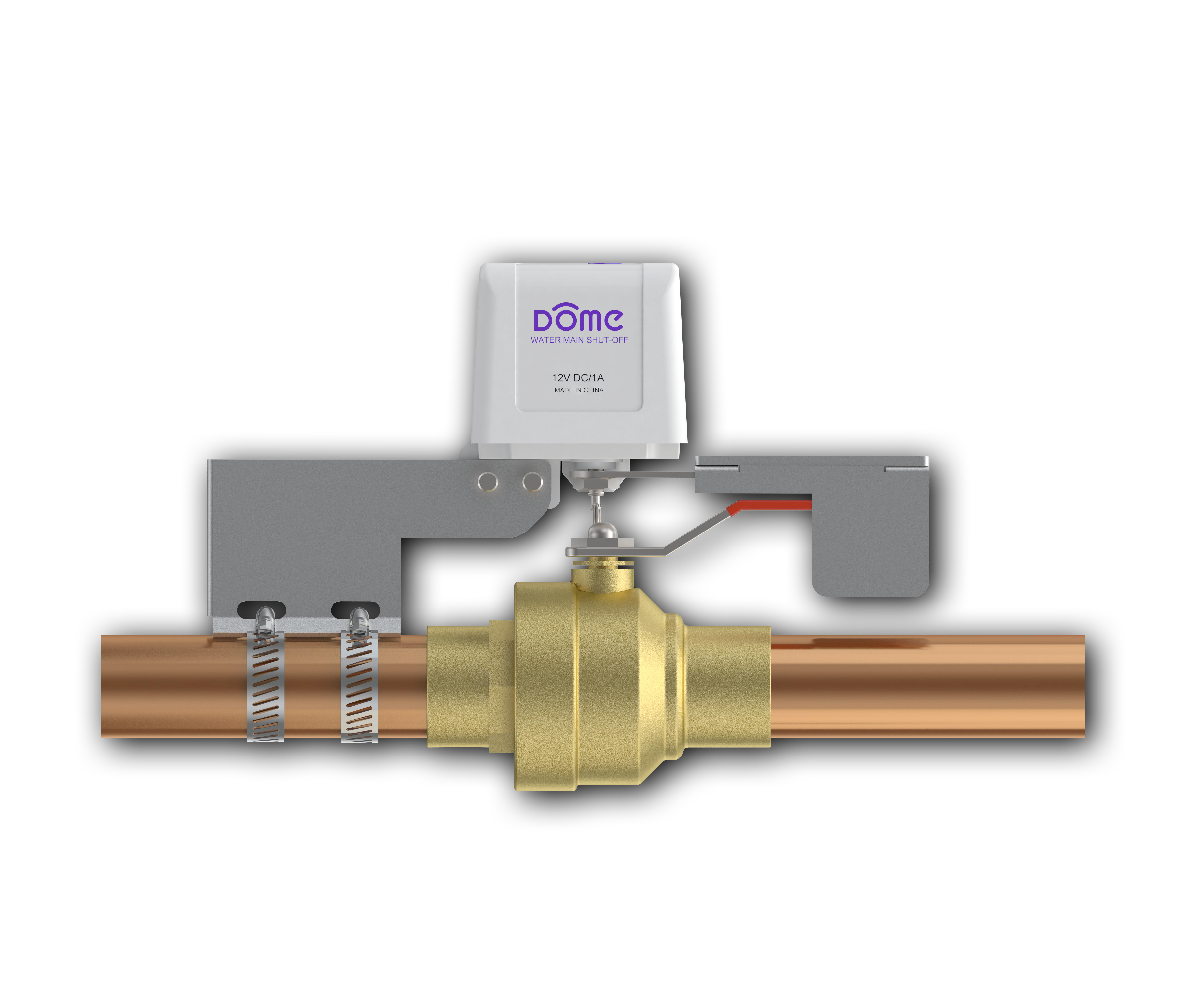
Description & Features
The Dome Water Main Shut-Off is a Z-Wave Plus Certified device that installs over any standard 1/2” to 1-1/2” ball valve, and opens or closes the valve when given a signal. The Water Main Shut-Off consists of three main parts - the “MOTOR ASSEMBLY,” the “MOUNTING BRACKET,” and the “CONTROL ARM.” The MOUNTING BRACKET is clamped onto the pipe with HOSE CLAMPS and the CONTROL ARM secures around the VALVE HANDLE to control the valve, while the MOTOR ASSEMBLY connects to your home automation system and ties everything together.
Key Features
- Open or close any valve remotely
- Single-tool installation
- Install over existing valve - no need for a plumber!
- Use with 1/2” to 1 1/2” size ¼-turn flat handle brass ball valves
- Z-Wave Plus Certified
- Up to 150’ range
- Pair with Flood Sensors to automatically shut off your water when there is a leak anywhere in your home.
Specifications
Technical Specifications
| Spec | Value |
|---|---|
| Radio protocol | Z-Wave(500 series) |
| Power supply | 12VDC |
| Working current | 35mA |
| Power Consumption | 0.13W |
| Operating Temperature | 32 - 112 °F |
| Radio frequency | 908.4 MHz US |
| Range | Up to 150’ depending on environment |
| Dimensions (L x W x H) | Sensor: 2.5” x 3.5” x 6” |
| Package Contents | User Manual, Water Main Shut-Off, Power Supply |
Inclusion & Exclusion
Figure 1 - Main Parts of the Water Main Shut-Off
Figure 2 - Underside of the Water Main Shut-Off
Inclusion
- For proper inclusion, bring the Water Main Shut-Off to the final location where it will be used. *
- Follow the instructions for your Z-Wave controller to enter inclusion mode.
- Make sure the Water Main Shut-Off is powered on, and when prompted by your controller, press the “open/close” button quickly 3 times in a row. The LED will stop blinking and stay on continuously upon successful inclusion.
Exclusion
- Follow the instructions for your Z-Wave certified Controller to enter exclusion mode.
-
When prompted, press the “open/close” button on the Shut-Off quickly 3 times
in a row.
The LED Indicator will flash five times indicating exclusion/disconnection.
Factory Reset & Misc. Functions
Resetting the Water Main Shut-Off
If needed, the Water Main Shut-Off can be reset locally by following these steps.
- Confirm that your Water Main Shut-Off is powered up.
- Press and hold the OPEN/CLOSE BUTTON for at least 10 seconds then release. A flashing LED INDICATOR indicates a successful factory reset.
- The Water Main Shut-Off’s memory will be erased to factory settings.
Emergency Operation
The Water Main Shut-Off can be operated manually in the event of a power outage, loss of communication with your Z-Wave Hub, or some other emergency. Follow these instructions to manually operate the Shut-Off:
- Unplug the power from your device.
-
Locate the MOTOR CLUTCH on the underside of your device (Fig 3,) and pull it outward by
the keychain ring. The CONTROL ARM will disengage from the motor and move freely.
Physical Installation
Review the Pre-Installation Checklist below to make sure the Water Main Shut-Off can be used for your application. The device should already be included in your Z-Wave system before continuing further.
Pre-Installation Checklist
Figure 4 - Required Clearance for the Water Main Shut-Off.
- The Water Main Shut-Off can be installed on any 1/2” to 1-1/2” brass ball valve
- Make sure the VALVE HANDLE is comfortably usable by hand prior to installation
- The valve should be 5” away from any walls or other obstructions (Figure 3)
- Make sure the OPEN/CLOSE BUTTON is accessible in the final position
- Make sure there is a working power outlet (that will always be powered on) reachable with a 10’ cord from the valve
- Finally, confirm that you are still within range of your Z-Wave controller.
Installation Process
Figure 5 - Installing the Water Main Shut-Off
Figure 6 - Aligning the Water Main Shut-Off
- Make sure the installed valve is comfortably usable by hand before continuing further.
- Open both HOSE CLAMPS completely so their ends are free, insert both of them into the slots in the MOUNTING BRACKET, and let them hang loosely.
- Remove the protective film covering the screws on the CONTROL ARM and spread the CONTROL ARM.
- Make sure both the valve and the Water Main Shut-Offare in the “open” position (where the handle is in line with the pipe, not at a right angle to it,) and slide the CONTROL ARM around the valve’s handle.
-
Loosely tighten the hose clamps around the pipe on the opposite side of the valve handle
so it remains moveable.
- Position the bolt of the Water Main Shut-Off directly above the bolt of the ball valve, and tighten the HOSE CLAMPS until the Shut-Off is completely secure (Figure 5.)
- Squeeze the CONTROL ARM closed around the valve handle and secure it tightly with the four screws previously covered by the protective film.
- To test for proper installation, power up the device and press the OPEN/CLOSE BUTTON. The motor will engage and your valve will close.
LED Behavior
| Color | Behavior | This happens when… |
|---|---|---|
| Blue | Blink Continuously | …the device is not yet included in a Z-Wave Network. |
| On Continulously | …the device is included in a Z-Wave Network and is in the “Closed” position. | |
| Off Continuously | …the device isincluded in a Z-Wave Network and is in the “Open” position. |
Table 2 - LED Behavior
Button Behavior
| Action | Condition | Result |
|---|---|---|
| Press the Button Once | All Conditions | Open or Close Valve |
| Push OPEN/CLOSE BUTTON 3 Times | Water Main Shut-Off Already Included in System | Device sends node info to Group 1 |
| Water Main Shut-Off Already Included in System and Controller is in Exclusion Mode | Device is excluded from the system and removes the Home ID from its memory | |
| Water Main Shut-Off Not Yet Included in System | Device enters inclusion mode and includes into whichever network is also in inclusion mode | |
| Press and hold OPEN/CLOSE BUTTON for 10+ seconds | All Conditions | Device will be reset to factory settings, and a DEVICE_RESET_LOCALLY command will be sent to Node 1 |
Table 3 - Button Behavior
Compatible Command Classes
| Command Class | Notes | ||||||||||
|---|---|---|---|---|---|---|---|---|---|---|---|
| Device Reset Locally V1 (5A) | - | ||||||||||
| Powerlevel V1 (73) | - | ||||||||||
| Association Group Information V1 (59) | - | ||||||||||
| Basic V1 (20) | - | ||||||||||
| Binary Switch V1 (25) |
Binary Switch commands will open and close the Water Main Shut-Off. Binary Switch
Report commands are also used to communicate changes in device status (e.g. the Valve
opening/closing) to the controller. See below for Binary Switch status values and
their corresponding meaning within the Shut-Off:
Valve Open: FF Valve Closed: 00 |
||||||||||
| All Switch V1 (27) |
All Switch commands open and close the Water Main Shut-Off along with any other device
included in your Z-Wave Network. See the Z-Wave Command Class specifications for
details on how the All Switch command class is typically implemented. See below for
All Switch status values and their corresponding meaning within the Shut-Off:
Valve Open: FF Valve Closed: 00 |
||||||||||
| Z-Wave Plus Info V2 (5E) |
Returned Value: 01 05 00 0F 00 0F 00
|
||||||||||
| Version V2 (86) |
|
||||||||||
| Manufacturer Specific V2 (72) |
|
||||||||||
| Association V2 (85) |
Group 1
|
Table 4 - Compatible Command Classes
Door/Window Sensor Pro
Description & Features
The Dome Door/Window Sensor is a battery powered security-enabled* Z-Wave Plus magnetic reed switch that can monitor the status of doors, windows, and anything else that opens and closes. It can also report ambient temperature levels. The Door/Window Sensor consists of two parts - the “sensor,” and the “magnet.” The sensor has a “reed switch” inside, which is sensitive to the magnet’s presence when aligned properly and within the defined distance. When the sensor and magnet are brought together or pulled apart, the sensor will report its open/close status to its Z-Wave controller, and the encrypted wireless communication* ensures that user data remains secure. Because many manufacturers use Z-Wave to communicate, the Door/Window Sensor can interact with different products of different categories.
Key Features
- Temperature Sensor
- Up to 220’ range
- Ten-Year Battery Life
- Z-Wave Signal Strength Indication
- 1” Max distance between sensor & magnet
- Ultra-Narrow (1/4”) Magnet (for Placement Between Door and Casing)
- Z-Wave Plus Certified
- S0 Security-Enabled*
- Monitor doors, windows, medicine cabinets, drawers, garage doors, and many other openings
Specifications
Technical Specifications
| Spec | Value |
|---|---|
| Radio protocol | Z-Wave(500 series) |
| Power supply | Single CR14505 3.6V battery |
| Working current | 35mA |
| Standby current | 7uA |
| Radio frequency | 908.4 MHz US |
| Range | Up to 150’ depending on environment |
| Dimensions (L x W x H) |
Sensor: 2.9” x 0.85” x 0.87” (75 x 21 x 22 mm) Magnet: 1.6” x 0.25” x 0.5” (40 x 6.35 x 12 mm) |
| Package Contents | User Manual, Sensor, Magnet, Battery, Double-Stick Tape, 2x Screws, 2x Wall Anchors |
Inclusion & Exclusion
Figure 1 - Door/Window Sensor Exploded View
Figure 2 - Main Parts of the Door/Window Sensor
Inclusion - New Installation
- For proper inclusion, bring the Door/Window Sensor to the final location where it will be used*.
- Follow the instructions for your Z-Wave controller to enter inclusion mode.
- Remove the Battery Tab protruding from the Battery Tab Slit.
- The device will automatically enter inclusion mode for two minutes and the LED Indicator will alternate between green and red.
Upon successful inclusion the LED Indicator will flash green three times then stop blinking.
Inclusion - Re-Installation
- For proper inclusion, bring the Door/Window Sensorto the final location where it will be used*.
- Follow the instructions for your Z-Wave controller to enter inclusion mode.
- Remove the Sensor Cover and the LED Indicator will start blinking yellow.
- Press the Button quickly 3 times in a row.
- The device will enter inclusion mode for two minutes and the LED Indicator will alternate between green and red.
After successful inclusion, the LED Indicator will flash green three times then blink red until the cover is replaced.
Exclusion
Follow the instructions for your Z-Wave Certified Controller to enter exclusion mode. When prompted by the controller:
- Remove the SENSOR COVER and the LED Indicator will start blinking red.
- Press the Button quickly 3 times in a row.
The LED Indicator will flash green three times indicating exclusion/disconnection and will then continue flashing red (indicating tamper) until the cover is replaced.
Factory Reset & Misc. Functions
Resetting the Door/Window Sensor Pro
If needed, the Door/Window Sensor Pro can be reset locally by following these steps.
- Remove the Sensor Cover and confirm that your Door/Window Sensor is powered up.
- Wait for 5 seconds.
- Move the Magnet and Sensor Base in and out of the closed position 6 times.
- The LED Indicator will light up red for two seconds when reset successfully.
The Door/Window Sensor’s memory will be erased to factory settings.
Waking Up the Door/Window Sensor Pro
Because the Mouser is a battery powered device, it wakes up on regular intervals to give battery and other status updates to the controller, as well as to accept configuration settings from the controller. This helps to extend the battery life. The device can be forced to wake up to submit these reports or accept new settings immediately by simply pressing and holding the BUTTON for half a second. The LED INDICATOR will flash once indicating successful wake up.
Physical Installation
The Door/Window Sensor can be install with double stick tape or the provided screws. The device should already be included in your Z-Wave system before continuing further.
Pre-Installation Checklist
- The Magnet Assembly and Sensor Assembly should be less than 1-1/4” apart when closed (Figure 3.)
-
Hold the Magnet Assembly and Sensor Assembly in place by hand where you wish to install
them, move them in and out of the closed position, and make sure the LED Indicator
blinks in response. This will confirm that the door and frame are spaced correctly to
accommodate the sensor.
- When moving the Magnet and Sensor in and out of the closed position, a Green followed by another Green or Red LED Indicator corresponds to Excellent or Poor Z-Wave Signal strength respectively.
- Make sure the Sensor Cover Release Button will be accessible in the final position.
- The Magnet is small enough (only 1/4” wide) to fit in the groove between the door and the casing.
- Finally, confirm that you are still within range of your Z-Wave controller.
Figure 3 - Placing the Door/Window Sensor on the Door
Installation Using Double-Stick Tape
- Wipe the door and door-frame clean of dust and anything else that will interfere with the tape’s stickiness.
- Peel the double-stick tape and adhere the Sensor Assembly to the door surface.
- Repeat the process for the Magnet Assembly, making sure the Magnet Assembly, and Sensor Assembly are no more than 1-1/4” apart when closed. The lines on the sides of the Magnet Assembly, and Sensor Assembly should be in line.
- Open and close the door to make sure the sensor works as expected (the LED Indicator blinks) and that the signal reaches your Z-Wave controller.
Installation Using Screws
Figure 4 - Installing the Door/Window Sensor With Screws
- Remove the Sensor Cover and Battery from the Sensor Base and the Magnet Cover from the Magnet Base.
- Hold the Sensor Base in place and drive the included screws through the screw holes into the door.
- Repeat the process for the Magnet Assembly, making sure the Magnet Assembly, and Sensor Assembly are no more than 1-1/4” apart when the door is closed. The lines on the sides of the MAGNET and SENSOR should be in line.
- Replace the Battery, Sensor Cover, and Magnet Cover.
- Open and close the door to make sure the sensor works as expected (the LED Indicator blinks) and that the signal reaches your Z-Wave controller.
LED Behavior
| Color | Behavior | This happens when… |
|---|---|---|
| Green | Blinks Twice Within 5 Seconds | …the sensor Detects the Magnet (door) moving, and the Z-Wave signal reached the controller. |
| Blinks 3 times quickly | …the device is successfully included into the system. | |
| Red | Stays on for 2 seconds | …the device is reset to factory settings. |
| Blinks 3 Times quickly | … the Button is pressed 3 times quickly and the device is excluded from the network. | |
| Blinks indefinitely | …the Sensor Cover is removed and the device is already included in a system. | |
| Yellow (Green + Red) | Blinks Indefinitely | …the Sensor Cover is removed and the device is not yet included in a system. |
| Red & Green Alternating | Two Flashes (Green-Red) Within 5 Seconds | …the sensor Detects the Magnet moving away or getting close (as the Door is opened or closed) and the Z-Wave signal was not received. |
| Flashing in alternating colors | …the Door/Window Sensor is in inclusion mode. It will continue blinking and remain in inclusion mode for up to two minutes, until it is included in a system. |
Table 2 - LED Behavior
Button Behavior
| Action | Condition | Result |
|---|---|---|
| Open the Cover | Door/Window Sensor Not Yet Included in System | LED Indicator blinks yellow (red + green) until the Sensor Cover is replaced |
| Door/Window Sensor Already Included in System | Device sends a tamper notification to its controller, and the LED Indicator blinks red until the Sensor Cover is replaced | |
| Push CONNECT BUTTON 3 Times | Door/Window Sensor Already Included in System | Device sends node info to Group 1 |
| Door/Window Sensor Already Included, and Controller is in Exclusion Mode | Device is excluded from the system and removes the Home ID from its memory | |
| Door/Window Sensor Not Yet Included in System, and Controller is in Inclusion Mode | Device enters inclusion mode and includes into whichever network is also in inclusion mode | |
| Move the Magnet and Sensor In and Out of the Closed Position 6 Times with Cover Removed | Door/Window Sensor Already Included in System | Device will be reset to factory settings, and a DEVICE_RESET_LOCALLY command will be sent to Group 1 |
| Any condition (as long as the device has power) | The device’s memory will erase to factory default settings and any associations, configuration parameters, and other locally saved data will be lost | |
| Press the Button Once | Door/Window Sensor Is Already Included in System | Device sends a wake up notification to Node 1. |
Table 3 - Button Behavior
Compatible Command Classes
| Command Class | Notes | ||||||||||||||||
|---|---|---|---|---|---|---|---|---|---|---|---|---|---|---|---|---|---|
| Device Reset Locally V1 (5A) | - | ||||||||||||||||
| Powerlevel V1 (73) | - | ||||||||||||||||
| Battery V1(80) | - | ||||||||||||||||
| Association Group Information V1 (59) | - | ||||||||||||||||
| Z-Wave Plus Info V2 (5E) |
Returned Value: 01 06 00 0C 06 0C 06
|
||||||||||||||||
| Version V2 (86) |
|
||||||||||||||||
| Manufacturer Specific V2 (72) |
|
||||||||||||||||
| Multilevel Sensor (31) |
The Door/Window Sensor monitors ambient temperature levels and reports this data to
the main controller using the Multilevel Sensor command class if Configuration
Parameter 04 is set to 01 (this is off by default.) Configuration Parameter 05 is used
to “offset” the reported value (add or deduct a static number from the
reported value) and Configuration Parameter 06 switches between Celsius and
Fahrenheit.
|
||||||||||||||||
| Binary Sensor (30) |
If Configuration Parameter 03 is set to 01 or 02, the Door/Window Sensor sends a
Binary Sensor Report when opened or closed and also when tamper events are detected.
See below for the SENSOR_BINARY_REPORT parameters sent:
|
||||||||||||||||
| Association V2 (85) |
Group 1
Group 2
Group 3
Group 4
Group 5
|
||||||||||||||||
| Wake Up V2 (84) | The wake-up interval is set in seconds, and is 43,200 seconds (12 hours) by default. The wake-up interval can be set to any value from 300s (5 minutes) to 16,777,200s (about 190 days) in 60-second increments. | ||||||||||||||||
| Notification V4 (71) |
If Configuration Parameter 03 is set to 00 or 02, the Door/Window Sensor sends a
Notification Report to the main controller whenever the door is opened and closed and
also when tamper events are detected. Two different Notification Types are used to
achieve this.
|
||||||||||||||||
| Configuration V1(70) | See “Configuration” Command Class Parameters”. |
Table 4 - Compatible Command Classes
“Configuration” Command Class Parameters
Configuration parameters are sent using a standard syntax to ensure interoperability
between all manufacturers’ products. All values are represented using the
hexadecimal number system.
Typical syntax is as shown below. Note that the value
sent must be the exact size, in bytes, as accepted by the setting. The “extra”
spaces should be filled with zeros (see the “value” column below.)
Example Configuration Parameter: 02 02 00 0A
| Param # | Size | Value |
| 02 (Param #2) |
02 (2 Bytes) |
00 0A (Value) |
| Param # | Size | Name | Available Values | Default Value |
|---|---|---|---|---|
| 01 | This parameter enables or disables the LED Indicator flashing to indicate opening and closing events. The Door/Window Sensor will always flash the LED Indicator for inclusion, exclusion, tamper, and other system events. | |||
| 01 | Enable/Disable LED Indicator |
00 (Open/Close LED Indicator Disabled) 01 (Open/Close LED Indicator Enabled) |
01 (Open/Close LED Indicator Enabled) |
|
| 02 | This parameter switches the Notification or Binary Sensor report sent when the door opens or closes. If this parameter is set to 01, the Door/Window Sensor will report “closed” instead of “open”when the Magnet and Sensor are pulled apart. | |||
| 01 | Configure Open/Close Reports Sent |
00 (Reports Closed when Magnet is close) 01 (Reports Open when Magnet is close) |
00 (Reports Closed when Magnet is close) |
|
| 03 | By default, the Door/Window Sensor uses the Notification command class to communicate open/close and tamper events. If this Parameter is set to 1, the device will instead use the Binary Sensor command class. | |||
| 01 | Switch Between Notification and Binary Sensor Command Classes |
00 (Notification Command Class is Used) 01 (Binary Sensor Command Class is Used) |
00 (Notification Command Class is Used) |
|
| 04 | The Door/Window Sensor can also monitor and report ambient temperature conditions. However, temperature sensing functionality is disabled by default to save battery life, and this configuration parameter is used to enable or disable this feature. | |||
| 01 | Enable/Disable Temperature Sensor |
00 (Temperature Sensor Disabled) 01 (Temperature Sensor Enabled) |
00 (Temperature Sensor Disabled) |
|
| 05 | This Configuration Parameter can offset the temperature value reported by ± 125 degrees to compensate for temperature variances in a room - for example, the temperature near the ceiling in a room is significantly higher than the average temperature of the same room. This Parameter accepts a signed 8-bit value with an absolute value of up to 125, and its units are Dependant on Configuration Parameter 07 | |||
| 01 | Temperature offset |
00 ~ 7D (0°~125°) 83 ~ FF (-125° ~ -1°) |
00 (0° Offset) |
|
| 06 | The Door/Window Sensor can report temperature values in either Celsius or Fahrenheit, and this parameter allows the user to decide which unit is used. | |||
| 01 | Temperature Units |
00 (Temperature Reported in Fahrenheit) 01 (Temperature Reported in Celsius) |
00 (Temperature Reported in Fahrenheit) |
|
| 07 | This parameter sets the value sent by the Basic Set command to Association Group 2 (for more information, see “Association Group Info”.) | |||
| 01 | Basic Set Value (Group 2) |
00 (0/Turn Off Device) 01 ~ 63 (0-99) FF (255/Turn On Device) |
FF (255/Turn On Device) |
|
| 08 | This parameter sets the value sent by the Basic Set command to Association Group 4. The Door/Window Sensor sends a Basic Set command to Association Group 4 when the door or window opens (for more information, see “Association Group Info”.) | |||
| 01 | Basic Set Value (Group 2) |
00 (0/Turn Off Device) 01 ~ 63 (0-99) FF (255/Turn On Device) |
FF (255/Turn On Device) |
|
| 09 | This parameter sets the value sent by the Basic Set command to Association Group 4.The Door/Window Sensor sends a Basic Set command to Association Group 4 when the door or window opens (for more information, see “Association Group Info”.) | |||
| 01 | Basic Set Value (Group 4) |
00 (0/Turn Off Device) 01 ~ 63 (0-99) FF (-1/Turn On Device) |
FF (-1/Turn On Device) |
|
Table 5 - “Configuration” Command Class Parameters